IEC 104
The IEC 104 driver in VC Hub communicates with substation devices over IEC 60870-5-104. You can add one IEC104 device, configure communication parameters, enable it, and then bind I/O tags to IEC 104 points.
For bulk import/export workflows, see Batch Operation.
Connecting to an IEC 104 device
- On the Devices -> IEC 104 page, click the Add button.
- In the Add dialog, enter device information (the values below are examples; use your real project values):
- Device Name: IEC104_1
- Enable TLS: Disabled (or Enabled if your server requires TLS)
- Server1: 127.0.0.1
- Port1: 2404 or 19998 (TLS port)
- Common Address: 1
- Connection Timeout (ms): 10000
- Receive APDU Timeout (ms): 10000
- Command ACK Timeout (ms): 10000
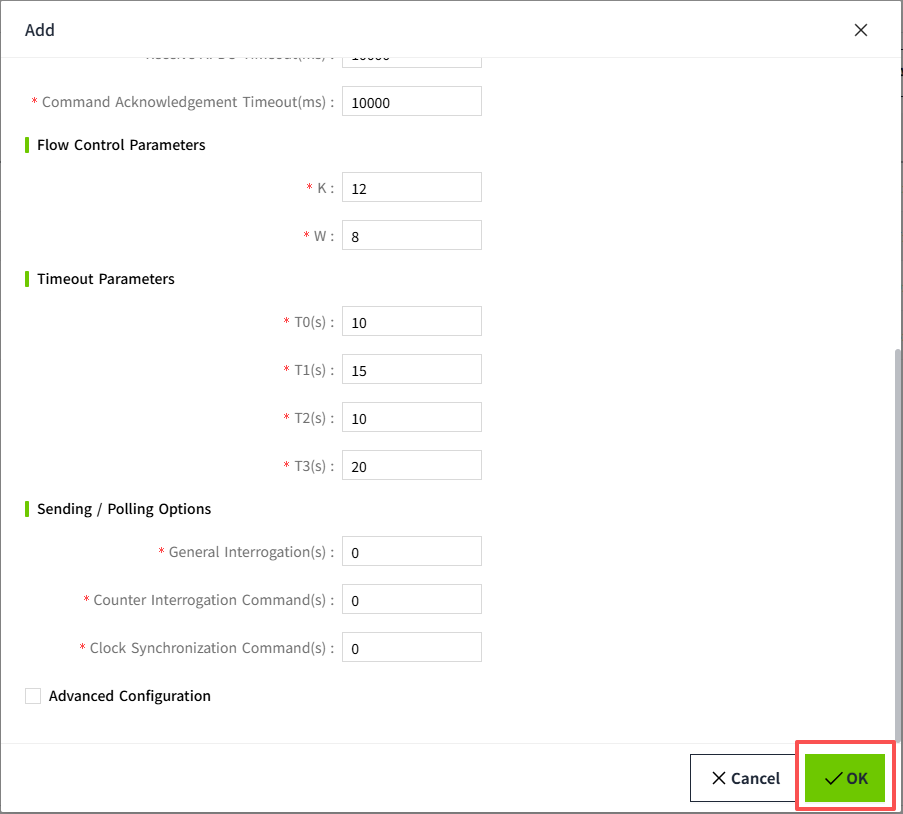
- Keep the default protocol parameters unless your device vendor requires different settings:
- K: 12
- W: 8
- T0: 30
- T1: 15
- T2: 10
- T3: 20
- Configure Sending / Polling Options according to your server behavior:
- General Interrogation(s): Number of general interrogation commands sent in one polling cycle.
- Counter Interrogation Command(s): Number of counter interrogation commands sent in one polling cycle.
- Clock Synchronization Command(s): Number of clock synchronization commands sent in one polling cycle.
- Configure Advanced Configuration (keep defaults unless your server requires custom frame formats):
- Originator Address: Originator address used in IEC104 frames (typically
0). - Cause of Transmission Length(bytes): Byte length of the COT field (typically
2). - Common Address Length(bytes): Byte length of the common address field (typically
2). - Information Object Address Length(bytes): Byte length of the IOA field (typically
3).
- Originator Address: Originator address used in IEC104 frames (typically
- (Optional) Click Test Connection next to the configured server before saving.
- Click OK. The new device is shown in the IEC104 device list.
- In the device list, turn on Enable Status for the device.

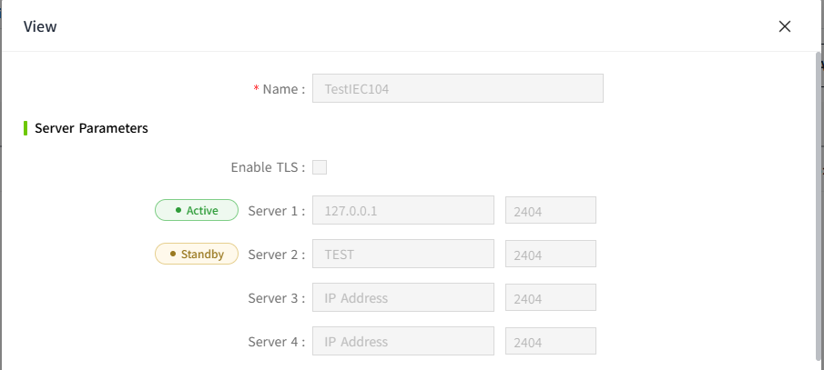
- On the device View page, server endpoint status is shown as Active or Standby. Only one endpoint can be Active: VC Hub checks endpoints in configured order and sets the first available endpoint to Active; once one endpoint is Active, all others remain Standby and are not connected.
- Active: the server endpoint currently in use for connection.
- Standby: configured endpoint not currently used for the active connection.
Configuration Fields
| Name | Description |
|---|---|
| Device Name | Name of the IEC 104 device connection. |
| Enable TLS | Enables TLS for IEC 104 communication. |
| Server1-Server4 | Up to 4 server IP/domain endpoints. |
| Port1-Port4 | Port for each server endpoint. |
| Test Connection | Verifies connectivity to the selected server endpoint. |
| Common Address | ASDU common address of the remote station. |
| Connection Timeout (ms) | Timeout for establishing TCP/TLS connection. |
| Receive APDU Timeout (ms) | Timeout for receiving IEC 104 APDU data. |
| Command ACK Timeout (ms) | Timeout waiting for command acknowledgment. |
| K / W | IEC 104 flow-control window parameters. |
| T0 / T1 / T2 / T3 | IEC104 timeout parameters (seconds). |
| General Interrogation Interval | Periodic GI interval. 0 means disabled. |
| Counter Interrogation Interval | Periodic counter interrogation interval. 0 means disabled. |
| Clock Synchronization Interval | Periodic clock sync interval. 0 means disabled. |
| Originator Address | Originator address used in IEC104 frames. |
| Cause Of Transmission Length | Byte length of COT field (1-2). |
| Common Address Length | Byte length of common address field (1-2). |
| Information Object Address Length | Byte length of IOA field (1-3). |
Notes:
- Enable Status controls whether VC Hub attempts connection; Connection Status shows whether communication is currently established.
- Enable All and Disable All are to enable or disable all data in the list.
- GI/CI/CS intervals should match the capabilities of the target IEC104 server to avoid frequent request.
Tag Binding
Bind I/O tags to data points from your IEC 104 device.
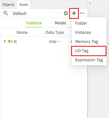
-
Create an I/O tag in the editor.
-
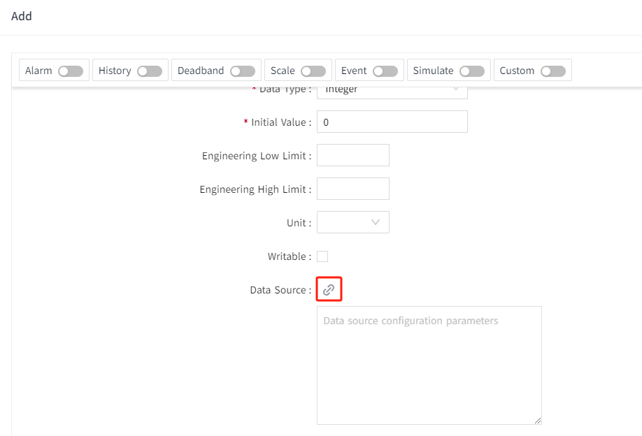
Open the tag edit page and click the data source binding button.
-
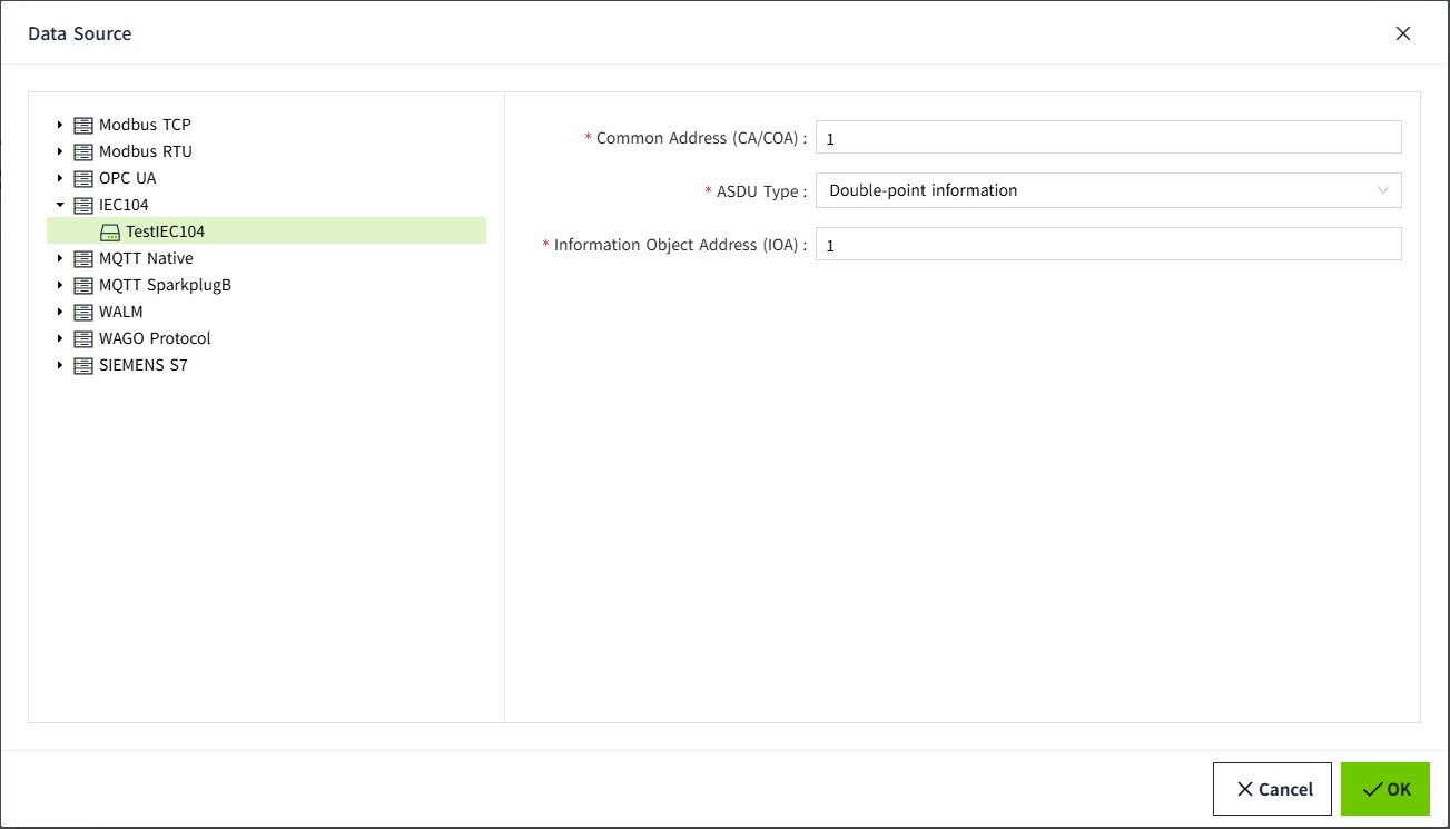
In the Data Source dialog, select the target IEC 104 device and fill in:
- Common Address
- ASDU Type
- Information Object Address
-
Click OK to finish binding.
Configuration Fields
| Name | Description |
|---|---|
| Device Name | IEC 104 device selected from the device tree. |
| Common Address | Common address used by this tag binding (positive integer). |
| ASDU Type | IEC 104 ASDU Type ID; options are filtered by the tag data type. |
| Information Object Address | IEC 104 IOA for the target point (positive integer). |
Type ID selection by tag data type
| Tag Data Type | Typical Type ID options |
|---|---|
| Bool | <1> M_SP_NA_1 <30> M_SP_TB_1 <3> M_DP_NA_1 <31> M_DP_TB_1 <45> C_SC_NA_1 <58> C_SC_TA_1 <46> C_DC_NA_1 <59> C_DC_TA_1 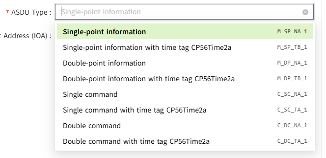 |
| Integer | <3> M_DP_NA_1 <31> M_DP_TB_1 <11> M_ME_NB_1 <35> M_ME_TE_1 <49> C_SE_NB_1 <62> C_SE_TB_1 <46> C_DC_NA_1 <59> C_DC_TA_1 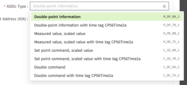 |
| Double | <9> M_ME_NA_1 <34> M_ME_TD_1 <11> M_ME_NB_1 <31> M_ME_TE_1 <13> M_ME_NC_1 <36> M_ME_TF_1 <48> C_SE_NA_1 <61> C_SE_TA_1 <49> C_SE_NB_1 <62> C_SE_TB_1 <50> C_SE_NC_1 <63> C_SE_TC_1 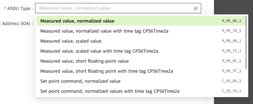 |